Mastering Tinkercad Corn Feild isn’t just about crafting a single model—it’s about building a repeatable workflow that scales from a lone plant to a full field. In this guide, you’ll learn practical 3D modeling techniques and tips to create a convincing corn field in Tinkercad, from simple stalks to orderly rows and natural variation. Whether you’re preparing a classroom project or a product mockup, this path will help you master Tinkercad Corn Feild with confidence.
Mastering Tinkercad Corn Feild: Overview and Goals

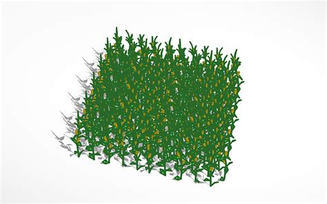
This section frames what you can achieve when you tackle a Tinkercad Corn Feild project. The goal is to build modular plant units that you can repeat with precise spacing, adjust for scale, and combine into a cohesive field scene. By keeping elements lightweight and parameter-driven, you’ll edit height, density, and color without reworking every component. The focus remains on clarity, speed, and accuracy in the final render or print-ready file of the Tinkercad Corn Feild.
Key Points
- Plan the field layout on the Tinkercad grid to maintain consistent row spacing.
- Model corn plants as modular units (stalk, leaves, ears) for easy duplication.
- Introduce variation in height, leaf angle, and stalk thickness to avoid a uniform look.
- Use alignment and grouping to assemble multiple plants into rows quickly.
- Prepare for export by checking units, file size, and color definitions for realism.
Core 3D Modeling Techniques for Tinkercad Corn Feild

Approach the corn field as a collection of reusable plant modules. Start with a tall stalk built from a tapered cylinder, add leaves shaped from elongated boxes with rounded edges, and place small ear clusters using cones or spheres. Group these parts into a single plant unit and then duplicate across the field. By treating the field as a grid of modules, you can experiment with density and spacing without rebuilding each plant.
Stalks, Leaves, and Ears
Construct the stalk from a cylinder with a slight taper, then attach several leaves that extend outward at varied angles using stretched boxes. For an ear of corn, use a small cone or a rounded box, positioned toward the top of the stalk. Keep the proportions in mind—stalk height can range from 70% to 110% of the base plant height to reflect natural variation.
Row Alignment and Field Layout
Duplicate the plant unit along one axis, then duplicate the entire row along the perpendicular axis. Use the Align tool to maintain consistent spacing and avoid overlaps. A simple starting spacing of 15–25 mm between plants, adjusted to your model’s scale, keeps the field readable in both renderings and prints.
Practical Tips for Realism
Realism comes from thoughtful variation and clean organization. Use multiple plants with small percentage changes in height, leaf curvature, and color shade. Subtle imperceptible differences, when repeated across a grid, create a believable field without heavy effort.
- Color and texture: Apply a slightly different green palette to stalks, leaves, and ears to mimic natural color variation. Use emulated shading by selecting lighter greens for sun-facing surfaces.
- Leaf variety: Mix up leaf length and curvature—some leaves are broad, others narrow; some curve upward, others hang slightly downward.
- Density control: Vary the number of plants per row in different sections to suggest growth fronts or crop rotation.
- Anchor details: Add a faint soil base or subtle texture under the rows to ground the field visually.
- Performance tip: keep the vertex count low by using simple shapes and combining where possible; this helps with faster renders and easier exports.
Exporting, Rendering, and Sharing Your Tinkercad Corn Feild
When you’re ready to export, check that your model uses consistent units (millimeters are common for 3D printing). Group related components, name parts clearly, and consider creating a low-poly version for distant renders. If you plan to animate or composite with other scenes, export as a compatible format (such as STL or OBJ) and keep texture information minimal but meaningful for the final presentation of your Tinkercad Corn Feild.
How do I model corn stalks efficiently in Tinkercad?
+Start with a tall cylinder that tapers toward the top, then add a few elongated leaves using rounded boxes. Group the stalk and leaves as a single plant unit and duplicate to form rows. Variations in height and leaf angle prevent a stiff, robotic look.
What’s a simple way to create realistic leaf shapes?
+Use elongated boxes with rounded corners, then stretch and rotate to mimic natural leaf spread. Combine several leaves per plant and subtly adjust their width and curvature to avoid uniformity.
Can I export my Tinkercad corn field for 3D printing?
+Yes. Ensure units are set to millimeters, check wall thickness, and export as STL or OBJ. A simplified version with fewer polygons will print more reliably, while a detailed version is better for high-quality renders.
How can I achieve even row spacing without manual counting?
+Use the duplicate feature along a single axis, then use the Align tool to fix spacing consistently. For large fields, set a fixed interval (for example, 20 mm) and apply it across the entire row.
Is animation possible in Tinkercad for a corn field?
+Tinkercad doesn’t support built-in animation. You can export multiple static frames and assemble an animation in separate software, or import the model into a program that handles animation and lighting for dynamic presentations.